BLOGGER TEMPLATES - TWITTER BACKGROUNDS

Wednesday, April 28, 2010

Antivirus Install

If you don't know what your operating system is perform the following steps:

1. Click the Start button and select Run.


2. Type winver into the run box shown below then click the OK button.


3. If you get a window that looks like the one below then you have Windows XP. Click on the link to go to the instruction page.


4. If you get a window that looks like the one below then you have Windows 2000. Click on the link to go to the instruction page.


5. If you get a window that looks like the one below then you have Windows Vista. Click on the link to go to the instruction page.

How to install Office 2007

Step 1: Insert the Microsoft Office 2007 Enterprise CD. If the Setup Wizard does not automatically begin, then click Start > Run > D:\setup.exe

Step 2: Enter the Product Key from the back of the CD jacket. Note: This is a unique code. Please keep in a safe place!

Click Continue.

Step 3: Check the box "I accept the terms of this agreement" and click the Continue button.

Step 4: Choose an installation option, Upgrade (removes Office 2003) or Customize (keeps Office 2003 installed and adds Office 2007, allowing you to use them both).

Note: Outlook 2003 will be uninstalled in either option. Outlook will be updated and your user settings and mail will migrate to the new version.

If you click Upgrade, go on to Step 5.

If you click Customize, go on to Step 4a.

Step 4a: Click the radio button for "Keep all previous versions."

Click the Installation Options tab, left-click the first drop down box and click Run all from My Computer

Click Install Now.

Step 5: Installation will begin. It may take 15-30 minutes to finish.

Step 6: Click Close to complete the installation.

Step 7: The first time you launch any Office program, you will be prompted to activate the software. As long as you have an active Internet connection, choose the default option and click Next.

Step 8: When the activation finishes, click Close.

Step 9: Click OK to finish.

Cara Memformat Harddisk

Langkah dan Tahap Format Ulang Hard Disk :

1. Back up file penting anda yang ada pada hardisk karena perintah format ini akan menghapus semua file yang ada di hard disk anda. Jika anda punya cd-rw drive atau dvd-rw drive anda bisa membuat cadangan dengan cara membakar file anda ke dalam cd atau dvd, atau kalau tidak punya CD RW, gunakan saja flash disk, itu pun kalau cukup untuk menampung data-data anda.

2. Lalu langkah selanjutnya adalah membuat windows

boot disk / rescue disk pada disket floppy 1.4 MB. Disket ini bertujuan untuk booting langsung ke disket tidak melalui harddisk anda. Istilahnya anda akan menggunakan os microsoft dos yang ada pada disket yang anda buat.

3. Kalau tidak punya DOS, coba pinjam atau beli CD yang berisi DOS, saya dulu mendapatkannya di tempat kursus, jadi tidak perlu membuat sistem di disket. Tinggal masukkan saja, pakai untuk bootable.

4. Ganti Setting Bios Ketika komputer dinyalakan anda harus langsung masuk ke tampilan bios untuk setting pilihan urutan boot. Ketika komputer baru dinyalakan, tekan tombol delete sampai bios muncul di layar monitor komputer anda. Ganti urutan booting dengan urutan pertama floppy disk.

5. Format Hard Disk. Setelah urutan boot di bios diganti, anda masukkan disket kemudian restart komputer anda. Nanti komputer anda akan otomatis membooting dari disket tersebut dan pilih boot without cd-rom supaya proses booting bisa lebih cepat. Setelah masuk ke command prompt a:\ , ketik format c: lalu tekan enter. Hal yang sama bisa diterapkan ke partisi harddik yang lain disesuaikan dengan jumlah partisi anda yang ada. Jika anda punya partisi 3 buah maka tambah perintah format d: dan format e:.

6. Kalau anda menggunakan CD bootable, tinggal masukkan saja, otomatis akan muncul DOS begitu di booting.

Kini harddisk anda menjadi seperti baru kembali.

Tuesday, April 20, 2010

IP ADDRESS

An Internet Protocol (IP) address is a numerical label that is assigned to devices participating in a computer network, that uses the Internet Protocol for communication between its nodes.[1] An IP address serves two principal functions: host or network interface identification and location addressing. Its role has been characterized as follows: "A name indicates what we seek. An address indicates where it is. A route indicates how to get there."[2]

The designers of TCP/IP defined an IP address as a 32-bit number[1] and this system, known as Internet Protocol Version 4 or IPv4, is still in use today. However, due to the enormous growth of the Internet and the resulting depletion of available addresses, a new addressing system (IPv6), using 128 bits for the address, was developed in 1995[3] and last standardized by in 1998.[4] Although IP addresses are stored as binary numbers, they are usually displayed in human-readable notations, such as 208.77.188.166 (for IPv4), and 2001:db8:0:1234:0:567:1:1 (for IPv6).

The Internet Protocol also routes data packets between networks; IP addresses specify the locations of the source and destination nodes in thetopology of the routing system. For this purpose, some of the bits in an IP address are used to designate a subnetwork. The number of these bits is indicated in CIDR notation, appended to the IP address; e.g., 208.77.188.166/24.

As the development of private networks raised the threat of IPv4 address exhaustion, set aside a group of private address spaces that may be used by anyone on private networks. They are often used with network address translators to connect to the global public Internet.

The Internet Assigned Numbers Authority (IANA), which manages the IP address space allocations globally, cooperates with five Regional Internet Registries (RIRs) to allocate IP address blocks to Local Internet Registries (Internet service providers) and other entities.

colour code

FFF
FFF
CCC
CCC
999
999
666
666
333
333
000
000
FFC
C00
FF9
900
FF6
600
FF3
300
SWITCH TO DECIMAL RGB
COLOR CODES
99C
C00
CC9
900
FFC
C33
FFC
C66
FF9
966
FF6
633
CC3
300
CC0
033
CCF
F00
CCF
F33
333
300
666
600
999
900
CCC
C00
FFF
F00
CC9
933
CC6
633
330
000
660
000
990
000
CC0
000
FF0
000
FF3
366
FF0
033
99F
F00
CCF
F66
99C
C33
666
633
999
933
CCC
C33
FFF
F33
996
600
993
300
663
333
993
333
CC3
333
FF3
333
CC3
366
FF6
699
FF0
066
66F
F00
99F
F66
66C
C33
669
900
999
966
CCC
C66
FFF
F66
996
633
663
300
996
666
CC6
666
FF6
666
990
033
CC3
399
FF6
6CC
FF0
099
33F
F00
66F
F33
339
900
66C
C00
99F
F33
CCC
C99
FFF
F99
CC9
966
CC6
600
CC9
999
FF9
999
FF3
399
CC0
066
990
066
FF3
3CC
FF0
0CC
00C
C00
33C
C00
336
600
669
933
99C
C66
CCF
F99
FFF
FCC
FFC
C99
FF9
933
FFC
CCC
FF9
9CC
CC6
699
993
366
660
033
CC0
099
330
033
33C
C33
66C
C66
00F
F00
33F
F33
66F
F66
99F
F99
CCF
FCC
CC9
9CC
996
699
993
399
990
099
663
366
660
066
006
600
336
633
009
900
339
933
669
966
99C
C99
FFC
CFF
FF9
9FF
FF6
6FF
FF3
3FF
FF0
0FF
CC6
6CC
CC3
3CC
003
300
00C
C33
006
633
339
966
66C
C99
99F
FCC
CCF
FFF
339
9FF
99C
CFF
CCC
CFF
CC9
9FF
996
6CC
663
399
330
066
990
0CC
CC0
0CC
00F
F33
33F
F66
009
933
00C
C66
33F
F99
99F
FFF
99C
CCC
006
6CC
669
9CC
999
9FF
999
9CC
993
3FF
660
0CC
660
099
CC3
3FF
CC0
0FF
00F
F66
66F
F99
33C
C66
009
966
66F
FFF
66C
CCC
669
999
003
366
336
699
666
6FF
666
6CC
666
699
330
099
993
3CC
CC6
6FF
990
0FF
00F
F99
66F
FCC
33C
C99
33F
FFF
33C
CCC
339
999
336
666
006
699
003
399
333
3FF
333
3CC
333
399
333
366
663
3CC
996
6FF
660
0FF
00F
FCC
33F
FCC
00F
FFF
00C
CCC
009
999
006
666
003
333
339
9CC
336
6CC
000
0FF
000
0CC
000
099
000
066
000
033
663
3FF
330
0FF
00C
C99
© 2006 VisiBone009
9CC
33C
CFF
66C
CFF
669
9FF
336
6FF
003
3CC
330
0CC
00C
CFF
009
9FF
006
6FF
003
3FF

Here are 216 web color codes. There are a variety of ways to color web sites. These hexadecimal codes can be used in both XHTML and CSS. Decimal color codes can be used in CSS and most graphics tools. Tip: adjust your font size to zoom in and out.


straight cable cat5

LANshack.com was the very first ecommerce website to offer free online tutorials for cable connections. To say that our articles have been popular over the span of many years would be an understatement. But time marches on and we now have three major updates. For one, we have updated this very popular tutorial, and two, we now have a video tutorial to go with it. But most importantly, we have now developed a totally new system for termination cables called the “Quick-Cat™ System”

Wow! After over 10 Years of working with cables, tools and connectors, and after keeping on top of our tool, cable, and connector suppliers, we have put it all together to formulate this system for the present a future of cabling components. What does all this mean to the consumer?
Compatibility, Reliability, Dependability, ease of use and virtually fool-proof and repeatable results.

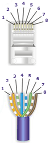
Due to an overwhelming response to our category 5 & 6 tutorial, and many requests for information and wiring diagrams of "straight through" and "crossover" (cross-pinned) patch cords, I have made this informational page and technical video. On this page, we will cover making patch cords, and other technical and non-technical issues relating to category 5 and 6 patching and connectivity from device to device. Below, you will find the diagrams for 568A, 568B, and crossover patch cables. I suggest that you read on, past the diagrams for some very useful and important information.

As always, there continues to be Controversies over standards and practices regarding the use and making of patch cords, and UTP cable in general. Please see our section below titled: "Controversies and Caveats : Category 5, 5E, and Cat 6 Patch Cables". I hope that you will find it interesting and informative.


--Tony Casazza, RCDD


568-B Wiring


Pair #WirePin #
1-White/BlueWhite/Blue5
Blue/White4
2-Wht./OrangeWhite/Orange1
Orange White2
3-White/GreenWhite/Green3
Green/White6
4-White/BrownWhite/Brown7
Brown/White8
<>

568-A Wiring


Pair #WirePin #
1-White/BlueWhite/Blue5
Blue/White4
2-White/GreenWhite/Green1
Green/White2
3-White/OrangeWhite/Orange3
Orange/White6
4-White/BrownWhite/Brown7
Brown/White8
<>

cross cable cat5

How-to: Do it yourself Ethernet Crossover Cable

by: Larry Mingus Published: October 4, 1998

This how-to is for all of you that enjoy the DIY thing or have more time than money. It is far easier to buy a ready made cable but not near as fulfilling. Plus, there are those times when you need a cable now and can't get a ready made quick enough.

You will need a length of network cable (UTP-Cat5), preferably a factory assembled straight through cable that comfortably reaches each computer. Be careful and measure accurately you would hate to find out that following the baseboard of the wall you end up two feet short. On the other hand you don't want to use a fifty foot cable to connect two computers ten feet apart. Ethernet does not like coiled up excess cable. Consider making the cable with enough slack to allow servicing the computer without needing to unplug the cable.

The hardest part for most people will most likely be finding the RJ45 cable connectors. Check with your local computer stores that do network installations, most techs will give you a couple if you ask. Otherwise you will have to buy a five or ten pack. Make sure you get at least two, three is better. That way if you mess up you can just cut off the bad end and try again. Cut off the RJ45 connector from one end of the cable and prepare the end for the new RJ45 connector. I don't use measurements for stripping the cable end, I start by stripping at least 1 inch of the main cable insulation and then carefully trim the eight internal wires using the factory assembled end as a guide to the proper length. Just make sure that each wire is equal length and that the connector cable lock pinches the main cable insulation.

You don't need any fancy crimping tools to make one cable, just one normal size screw driver and one small screwdriver with a blade the same thickness' of the brass conductors in the RJ45 connector. You may need a second pair of hands to help hold the cable and RJ45 connector while you or your helper secures the connector cable lock. It's a little tricky to get all the wires into the proper holes but with a little patience anyone can do it. When it comes time to securing the connector cable lock use the normal size screwdriver that fits into the connector cable lock slot. It doesn't take a lot of pressure to seat the cable lock just tap lightly until the cable is secure.

Note: Make sure ALL wires are pushed completely into the connector before seating the connector cable lock.

Once the connector cable lock is secure it's time to move on to seating the brass wire conductors. This is probably the most tricky part, each wire has a separate brass conductor that needs to be seated to make contact with the wire. Once again you will want a second pair of hands to hold the RJ45 connector while you or your partner carefully seats each of the brass conductors. Lightly tap each conductor down with the small thin screwdriver to just below the plastic ridge, use the factory assembled end of the cable as a guide for how deep to seat the brass conductors.

Note: A pliers can be used to press down all the brass conductors at one time to the plastic ridges, then use the small thin blade screwdriver to finish seating to the proper recessed level.

That's it, if everything went well you now have an Ethernet UTP Category 5 crossover cable.

Crossover
Cable
Straight Through
Cable
RJ-45
PIN
RJ-45
PIN
RJ-45
PIN
RJ-45
PIN
1 Rx+3 Tx+1 Tx+1 Rc+
2 Rc-6 Tx-2 Tx-2 Rc-
3 Tx+1 Rc+3 Rc+3 Tx+
6 Tx-2 Rc-6 Rc-6 Tx-

Note: The standard connector view shown is color-coded for a straight thru cable


Category 5 wiring standards:

EIA/TIA 568A/568B and AT&T 258A define the wiring standards and allow for two different wiring color codes.

Pin #

Signal

EIA/TIA 568A

AT&T 258A, or EIA/TIA 568B

Ethernet 10BASE-T
100BASE-T

1

Transmit+

White/Green

White/Orange

X

2

Transmit-

Green/White
or Green

Orange/White
or Orange

X

3

Receive+

White/Orange

White/Green

X

4

N/A

Blue/White
or Blue

Blue/White
or Blue

Not used *

5

N/A

White/Blue

White/Blue

Not used *

6

Receive-

Orange/White
or Orange

Green/White
or Green

X

7

N/A

White/Brown

White/Brown

Not used *

8

N/A

Brown/White
or Brown

Brown/White
or Brown

Not used *

  • Pairs may be solid colors and not have the stripe.
  • Category 5 cable must use Category 5 rated connectors.

Only two pairs of wires in the eight-pin RJ-45 connector are used to carry Ethernet signals. Both 10BASE-T and 100BASE-T use the same pins, a crossover cablemade for one will also work with the other.

*Note: Even though pins 4,5,7, and 8 are not used, it is mandatory that they be present in the cable.